How to Model a Ceiling Fan on Angled Walls in Revit
Revit is a powerful Building Information Modeling (BIM) software utilized for architectural design, structural engineering, MEP engineering, and construction. Accurate modeling of building components is crucial for effective project coordination, clash detection, and energy analysis. Modeling a ceiling fan on angled walls presents specific challenges due to the sloping surface and the need to ensure the fan is correctly oriented and functional within the digital model. This article details the process of creating and placing a ceiling fan on an angled wall in Revit, focusing on parametric modeling techniques and best practices for achieving accurate results.
The process involves creating a custom ceiling fan family or using an existing one, modifying it to accommodate the angled wall, and then placing and adjusting the fan within the project environment. The key is to use appropriate reference planes and parameters to maintain the fan's orientation and functionality regardless of the wall's angle. Special attention must be paid to the fan's cut geometry and its impact on the ceiling and wall surfaces.
Key Point 1: Creating or Modifying a Ceiling Fan Family
The first step is to either create a new ceiling fan family or to modify an existing one. Creating a new family from scratch offers the greatest control over the fan's geometry and parameters, while modifying an existing family can save time if a suitable base model is available. Both approaches require careful planning and execution.
When creating a new family, start with a "Generic Model Ceiling Based" template. This template provides a pre-defined ceiling reference level which is essential for placing the fan correctly. Within the family editor, define the key parameters for the fan, such as its diameter, height, blade angle, and motor housing dimensions. These parameters will allow for easy customization and adjustments within the project.
Use extrusion, revolve, and sweep tools to create the fan's geometry. Ensure that all geometry is locked to the reference planes to maintain parametric control. For example, the diameter of the fan blades should be governed by a "Blade Diameter" parameter, and the height of the motor housing should be controlled by a "Motor Housing Height" parameter.
To accommodate the angled wall, a new reference plane must be created that is perpendicular to the wall's surface. This reference plane will serve as the host for the fan. In the family editor, create a vertical reference plane and name it appropriately, such as "Angled Wall Plane." This plane will ultimately be aligned with the angled wall in the project.
If modifying an existing family, the same principles apply. Identify the key parameters and geometry components that need adjustment to accommodate the angled wall. Add the "Angled Wall Plane" reference plane and adjust the existing geometry to align with it. It's important to ensure that the fan's origin point remains fixed and that the geometry adjusts parametrically based on the "Angled Wall Plane's" orientation.
Once the geometry is complete, assign appropriate materials to the different components of the fan. These materials should be parametric, allowing for easy customization within the project environment.
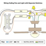
Finally, add a connector element to the fan family. This connector will allow the fan to be connected to the electrical system in the MEP model. The location of the connector should be carefully chosen to reflect the actual wiring connections. Define the connector's system type (e.g., Power – Balanced) and its voltage and amperage requirements.
Key Point 2: Placing and Aligning the Fan with the Angled Wall
Once the ceiling fan family is created or modified, it needs to be loaded into the Revit project and placed on the angled wall. This involves using specific alignment and work plane techniques to ensure the fan is correctly oriented and positioned. The first step is to model the angled wall accurately.
In the Revit project, create or select the angled wall where the ceiling fan will be placed. The wall's angle should be defined accurately using the wall's properties. Note the wall's angle relative to the horizontal plane, as this information will be crucial for aligning the fan.
Load the ceiling fan family into the project. Use the "Place on Face" placement option to place the fan on the angled wall. This option allows the fan to automatically align with the wall's surface.
After placing the fan, use the "Align" tool to precisely position it on the wall. Select the "Angled Wall Plane" reference plane within the fan family and align it with the surface of the angled wall. This will ensure that the fan is perpendicular to the wall's surface.
If the fan is not aligning correctly, verify that the "Angled Wall Plane" is properly defined within the family and that the wall's angle is accurately modeled. Sometimes, adjusting the work plane of the fan family can resolve alignment issues. Use the "Pick New Host" option to re-host the fan to the angled wall.
Once the fan is aligned, use the "Move" and "Rotate" tools to fine-tune its position and orientation. Ensure that the fan is centered on the wall and that its blades have adequate clearance from any obstructions.
Verify that the fan's cut geometry is correctly interacting with the wall. The fan should create a clean opening in the wall without any overlapping or gaps. If necessary, adjust the cut geometry within the fan family to achieve the desired result.
Pay close attention to the view settings when placing and aligning the fan. Use a 3D view with fine detail and realistic visual style to accurately assess the fan's position and orientation. Switch between different views (e.g., plan view, elevation view, section view) to verify that the fan is correctly placed in all dimensions.
Key Point 3: Parameter Control and Adjustments
The final step is to utilize the parameters defined within the ceiling fan family to make any necessary adjustments to its size, shape, and materials. This allows for customization of the fan to match the specific design requirements of the project.
Select the ceiling fan in the Revit project and access its properties. This will display the parameters that were defined within the family editor. Adjust the parameters, such as "Blade Diameter," "Motor Housing Height," and "Blade Angle," to customize the fan's appearance.
If the fan's geometry is not responding correctly to parameter changes, review the family editor to ensure that all geometry is properly constrained to the reference planes. Incorrect constraints can cause unexpected behavior when adjusting parameters.
Utilize type catalogs to create different types of ceiling fans with pre-defined parameter values. This allows for easy selection of different fan sizes and styles within the project.
If the materials assigned to the fan components are parametric, adjust them to match the desired finish. Use the material browser to select different materials and apply them to the fan's components.
For complex fan designs, consider using formulas to link parameters together. For example, the "Blade Angle" parameter could be linked to the "Blade Diameter" parameter to ensure that the blade angle is automatically adjusted based on the fan's size.
Regularly test the parametric behavior of the fan by adjusting different parameters and verifying that the geometry updates correctly. This will help ensure that the fan remains functional and accurate throughout the project lifecycle.
When adjusting the fan's parameters, pay attention to the overall aesthetic and functionality of the space. Consider the fan's size and style in relation to the room's dimensions and design. Ensure that the fan provides adequate airflow without being visually overwhelming.
By carefully following these steps, it is possible to accurately model a ceiling fan on angled walls in Revit. The key is to use parametric modeling techniques, pay close attention to alignment and work plane settings, and regularly test the fan's behavior to ensure that it remains functional and accurate throughout the project lifecycle. Through the incorporation of custom components and parametric control, Revit models can become more robust and detailed, leading to better design outcomes.

How To Install A Ceiling Fan On Sloped Lemon Thistle

How To Choose A Ceiling Fan For Vaulted Ceilings Lightology

How To Install A Ceiling Fan Hunter

How To Install A Ceiling Fan On Sloped Lemon Thistle

Electrical Mount Ceiling Fan At The Peak Of A Sloped Home Improvement Stack Exchange

Diy Cathedral Mount Ceiling Fan Box The Shabinlife

How To Choose A Ceiling Fan For Vaulted Ceilings Lightology

Ensuring Proper Ceiling Fan Installation With Vaulted Ceilings

Cathedral Ceiling Fan Installation Instructions

How To Choose A Ceiling Fan For Vaulted Ceilings Lightology
Related Posts