How To Install A Ceiling Fan Remote Control (6 Wires)
Installing a ceiling fan remote control can significantly enhance convenience and control over a room's environment. This article provides a comprehensive guide for installing a remote control unit in a ceiling fan with six wires, a common configuration found in many fan models. However, it is crucial to remember that working with electricity can be hazardous. If one feels uncomfortable with any of the following steps, consulting a qualified electrician is strongly recommended.
Before beginning the installation process, gathering the necessary tools and materials is essential. Typically, this includes a screwdriver (Phillips and flathead), wire strippers, electrical tape, a ladder, and the new remote control kit. The remote control kit should contain a receiver unit, a remote transmitter, wire connectors, and installation instructions specific to the model. Always refer to the manufacturer's instructions as the primary guide, as wiring configurations might vary.
Safety is paramount when working with electrical fixtures. The first and most important step is to turn off the power to the ceiling fan circuit breaker at the main electrical panel. This prevents electrical shock and ensures a safe working environment. After turning off the breaker, verify the power is off by flipping the wall switch that controls the fan. If the fan does not operate, the power is off.
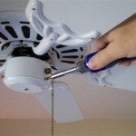
Once the power is confirmed off, the existing canopy covering the fan's electrical connections needs to be removed. This typically involves loosening screws holding the canopy to the ceiling mount. Carefully lower the canopy, exposing the wiring connections within the fan's housing. Note the existing wiring connections before disconnecting anything. Taking a picture with a phone or drawing a diagram can be helpful later during the re-wiring process.
Ceiling fans with six wires usually have separate wires for the fan motor and the light fixture. The wires are often color-coded, but it's prudent to verify their function using a voltage tester. With the power still off at the breaker, the voltage tester can identify the hot wire, neutral wire, and ground wire for both the fan and the light. This information is crucial for connecting the remote receiver correctly.
Now, the remote receiver can be integrated into the fan's wiring. The receiver typically has wires labeled to correspond with the fan's wires (e.g., fan hot, fan neutral, light hot, light neutral, etc.). Carefully connect the wires from the receiver to the corresponding wires from the fan and the house supply wires using the provided wire connectors. Ensure all connections are secure and tightly capped with the connectors. No bare wires should be exposed.
The specific wiring configuration varies depending on the remote control kit and the fan model. Consult the provided wiring diagrams in the remote control kit instructions to ensure accurate connections. Commonly, the receiver's black wire connects to the fan's and supply's black (hot) wires, the white receiver wire connects to the fan's and supply's white (neutral) wires, and the green receiver wire connects to the fan's and supply's green (ground) wires. The blue and red wires from the receiver typically connect to the fan motor’s similarly colored wires, controlling fan speed. The light kit wires follow a similar pattern.
After all wire connections are secure, carefully tuck the receiver unit and excess wiring into the fan's housing, ensuring they don't interfere with the fan's operation. Then, re-attach the canopy to the ceiling mount, ensuring it fits snugly and covers all wiring. Once the canopy is secure, the installation process moves to the wall switch.
At the wall switch, the existing wires need to be configured to allow the remote receiver to control the fan. Typically, this involves connecting the hot wire and the neutral wire together at the switch, effectively bypassing the switch and allowing constant power to reach the receiver. Cap off any unused wires with wire connectors and tuck them safely into the switch box.
Finally, restore power to the ceiling fan circuit by turning the breaker back on at the main electrical panel. Test the remote control by operating the fan and light. The fan speed and light should respond to the commands from the remote. If the fan does not operate correctly, double-check all wiring connections and consult the manufacturer's instructions. Ensure all wires are connected securely and to the correct terminals on both the receiver and within the fan housing.
Proper installation of the wall bracket or holder for the remote is the last step. This usually involves attaching the bracket to the wall with the provided screws and placing the remote in the holder. This keeps the remote easily accessible and prevents misplacement. With the remote in place, the installation is complete, providing convenient wireless control of the ceiling fan.

How To Wire A Ceiling Fan With Remote Receiver

How To Install A Ceiling Fan With Remote Control

How To Wire A Ceiling Fan Control Using Dimmer Switch

How To Wire A Ceiling Fan Control Using Dimmer Switch

Ceiling Fan Installation And Circuitry Explained Controller Two Switch Circuits Demonstrated

Electrical Ceiling Fan Wiring With Remote Control 2 Wall Switches Home Improvement Stack Exchange

Lighting How To Wire A Hunter Remote Ceiling Fan Exeter And Utilize Both Wall Switches Home Improvement Stack Exchange

How To Wire A Ceiling Fan Control Using Dimmer Switch

Universal Ceiling Fan Remote Replacement Ifixit Repair Guide

In Wall Ceiling Fan Remote Control How To Install Light Switch
Related Posts