What Is a Non-Suspended Ceiling in Revit?
Revit, a Building Information Modeling (BIM) software by Autodesk, allows users to create detailed 3D models of buildings. These models contain not just graphical representations but also embedded data related to building components. One such component is the ceiling. Within Revit, ceilings are categorized and modeled in various ways to reflect real-world construction practices. Understanding the difference between suspended and non-suspended ceilings is crucial for accurate modeling and documentation.
A "non-suspended ceiling" in Revit refers to a ceiling that is directly attached to the structure above, typically the floor or roof framing. It differs significantly from a suspended, or "dropped," ceiling, which hangs at a distance from the structural deck. The distinction lies in the method of attachment and the resulting spatial characteristics. Non-suspended ceilings offer a different set of design possibilities and require a different approach in Revit modeling.
To fully grasp the concept of a non-suspended ceiling, it's helpful to consider the alternative: the suspended ceiling. A suspended ceiling is constructed using a grid system hung from the structure above by wires or other supports. This creates a plenum space between the suspended ceiling plane and the structural deck, which is often used to house mechanical, electrical, and plumbing (MEP) systems. In contrast, a non-suspended ceiling is in direct contact with the floor or roof assembly.
Direct Attachment and Structural Integration
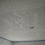
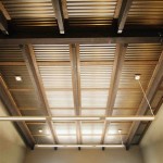
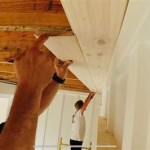
The primary characteristic of a non-suspended ceiling is its direct attachment to the building's structure. This means that the ceiling finish, whether it's gypsum board, wood panels, or another material, is applied directly to the underside of the floor or roof framing. This can be achieved in several ways, depending on the construction type. For example, in a wood-framed building, the ceiling finish might be attached directly to the joists. In a concrete building, it could be glued or mechanically fastened to the underside of the concrete slab.
This direct attachment has several implications for design and construction. First, it minimizes the overall height of the space. Because there is no suspended grid or plenum, the ceiling is as close to the structural deck as possible, maximizing headroom. This can be particularly important in buildings with limited floor-to-floor heights. Second, the absence of a plenum means that MEP services cannot be easily concealed above the ceiling. Instead, these services must be integrated into the floor or wall assemblies, or exposed as a design feature. Third, the structural performance of the ceiling can be more directly linked to the structure above. Any movement or deflection in the floor or roof will be directly transmitted to the ceiling finish, which could lead to cracking or other damage.
In Revit, modeling a non-suspended ceiling involves creating a ceiling element that is attached directly to the underside of the floor or roof. The "Height Offset from Level" parameter is typically set to zero, or a minimal value to account for the thickness of the finish material. The "Ceiling" tool in Revit allows for sketching the boundary of the ceiling and assigning a material and thickness. The properties of the ceiling can then be adjusted to accurately represent the construction details.
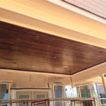
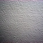
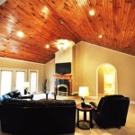
The material selection for a non-suspended ceiling is often driven by aesthetic considerations, acoustic performance, and fire resistance requirements. Gypsum board is a common choice for its fire-resistant properties and ability to be finished with paint or other coatings. Wood panels can provide a warmer aesthetic, while concrete can be left exposed for an industrial look. The choice of material will influence the overall design and the way the ceiling interacts with the space.
When modeling a non-suspended ceiling in Revit, it's important to accurately represent the connections between the ceiling finish and the structure above. This can involve adding details such as furring channels, clips, or other hardware that are used to attach the ceiling to the framing. These details can be modeled using Revit's families and components, which allows for a high level of accuracy and realism. Accurately representing these connections is essential for generating accurate quantity takeoffs and for coordinating the design with other trades.
Acoustic and Thermal Considerations
The acoustic and thermal performance of a non-suspended ceiling can differ significantly from that of a suspended ceiling. Because there is no plenum space, sound transmission through the ceiling is more direct. This means that soundproofing measures must be integrated into the ceiling assembly itself. This can involve adding layers of sound-dampening materials, such as mineral wool or acoustic panels, to the ceiling construction.
Similarly, the thermal performance of a non-suspended ceiling is directly related to the insulation in the floor or roof assembly above. If the insulation is inadequate, the ceiling can become a source of heat loss in the winter and heat gain in the summer. To improve the thermal performance of a non-suspended ceiling, it's important to ensure that the insulation is properly installed and that there are no gaps or voids that can allow air leakage. In some cases, it may be necessary to add additional insulation to the ceiling assembly to meet energy code requirements.
In Revit, the acoustic and thermal properties of a non-suspended ceiling can be modeled using the software's material properties and energy analysis tools. By assigning accurate material properties to the ceiling element, it's possible to estimate its acoustic and thermal performance. These estimates can then be used to evaluate the design and make adjustments as needed. Revit's energy analysis tools can also be used to simulate the energy performance of the building as a whole, taking into account the thermal properties of all of the building's components, including the non-suspended ceiling.
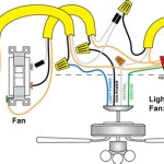
The lack of a plenum space in a non-suspended ceiling also affects the distribution of air and light. In a suspended ceiling, the plenum can be used to distribute conditioned air through diffusers or grilles. In a non-suspended ceiling, these devices must be integrated into the ceiling itself, or located in the walls or floors. Similarly, lighting fixtures must be surface-mounted or recessed into the ceiling, rather than suspended from the structural deck. This requires careful planning and coordination to ensure that the lighting and ventilation systems are properly integrated into the design.
When modeling these features in Revit, it's important to accurately represent the location and size of the diffusers, grilles, and lighting fixtures. This can be done using Revit's families and components, which allows fine-grained control over the appearance and behavior of these elements. By accurately modeling these features, it's possible to visualize the finished space and identify any potential conflicts or coordination issues.
Design and Construction Considerations in Revit
When using Revit, modeling a non-suspended ceiling requires careful attention to detail and a thorough understanding of the construction process. The key is to accurately represent the way the ceiling is attached to the structure above and to ensure that all of the necessary components, such as furring channels, clips, and insulation, are included in the model. This requires close collaboration between the architect, engineer, and contractor to ensure that the design is buildable and that all of the details are properly coordinated.
One of the challenges of modeling a non-suspended ceiling in Revit is that it can be difficult to represent the complex geometry and connections of the ceiling assembly. Revit's families and components can be used to create custom details that accurately represent these features, but this requires a significant investment of time and effort. It's also important to ensure that the details are properly documented and that they are consistent throughout the model. This can be achieved by creating a set of standard details that are used for all non-suspended ceilings in the project.
Another consideration when modeling a non-suspended ceiling in Revit is the impact on the overall performance of the building. As mentioned earlier, the acoustic and thermal performance of the ceiling are directly related to its construction details. By accurately modeling these details and assigning appropriate material properties, it's possible to estimate the performance of the ceiling and make adjustments as needed. This can help to ensure that the building meets its energy and acoustic performance goals.
Coordination with other trades is extremely important. Since there is no plenum space to easily accommodate services, the Revit model needs to accurately reflect the routing of any electrical conduits, plumbing lines, or HVAC ductwork that might run within the ceiling assembly. This requires close collaboration with the MEP engineers and contractors to ensure that there are no conflicts and that all of the services are properly supported. Clash detection tools within Revit can be utilized to identify potential conflicts early in the design process, preventing costly rework during construction.
Ultimately, accurately modeling a non-suspended ceiling in Revit necessitates a strong understanding of construction techniques, material properties, and the integration of various building systems. The software provides the tools needed to create a detailed and informative model, but the user must possess the knowledge and expertise to use those tools effectively. The creation of detailed families and components, coupled with careful coordination among project team members, ensures a successful and accurate representation of the non-suspended ceiling in the BIM model.

Designing Suspended Ceilings Knowledge Base Revit Linear

Fixed Ceiling Vs Suspended Ny Engineers

Solved False Ceiling Pattern Autodesk Community

Solved Ceiling Autodesk Community

Solved Ceiling Suspension Rod Length Adjust Autodesk Community

Make Ceiling Grids Actual And Not Part Of The Material Autodesk Community

Fixed Ceiling Vs Suspended Ny Engineers

Designing Suspended Ceilings Knowledge Base Revit Linear

How To Create Reflected Ceiling Plans In Revit Mashyo

Solved Ceiling Hosted Lights Not Attaching To Autodesk Community
Related Posts